
The effect of different aerodynamic elements on the efficiency of the McLaren MP4-29 front wing
This is by no means representative of the actual performance of McLaren’s aerodynamic packages. The CAD geometry was generated based on high quality pictures, but from different sources which also means that different camera settings were used, and no proper three view, making the task of getting an exact representation almost impossible. That being said, two additional settings were put to the test.
Contents
Removing elements
Two additional simulations at 200 kph (representative of the average speed in most circuits) were carried out to compare data against that of the original geometry. A first one without cascade and a second one without a vane and what we may call a diffuser.
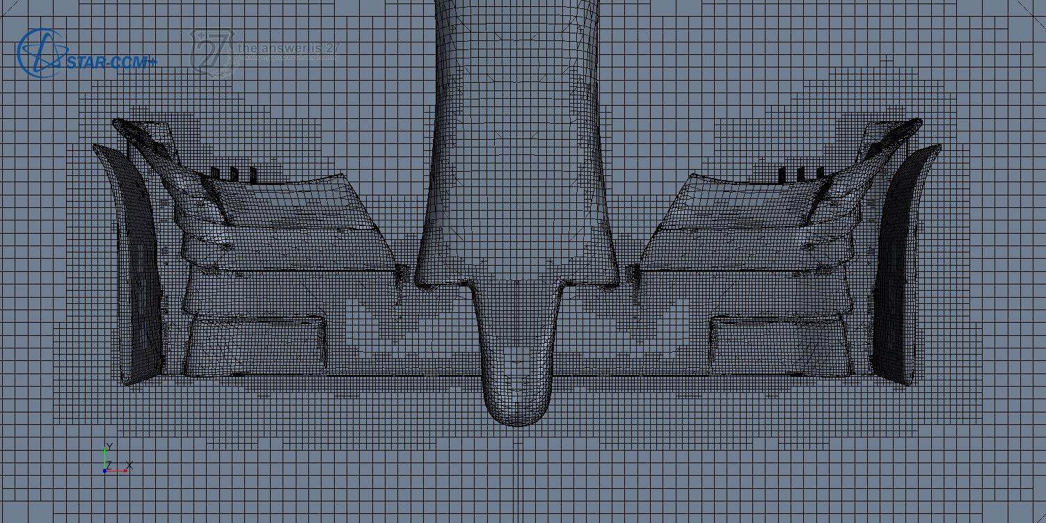
Mesh parameters, boundary conditions and turbulence models remain the same.
Results
Aerodynamics is not intuitive, and as such, intuition should not be relied on when trying to explain the effect of aerodynamic elements on the flow (see the following quote and video).
It’s easy to explain how a rocket works, but explaining how a wing works takes a rocket scientist.
Philippe Spalart
Why do I mention this? Well, take a look at this plot:
Cascade
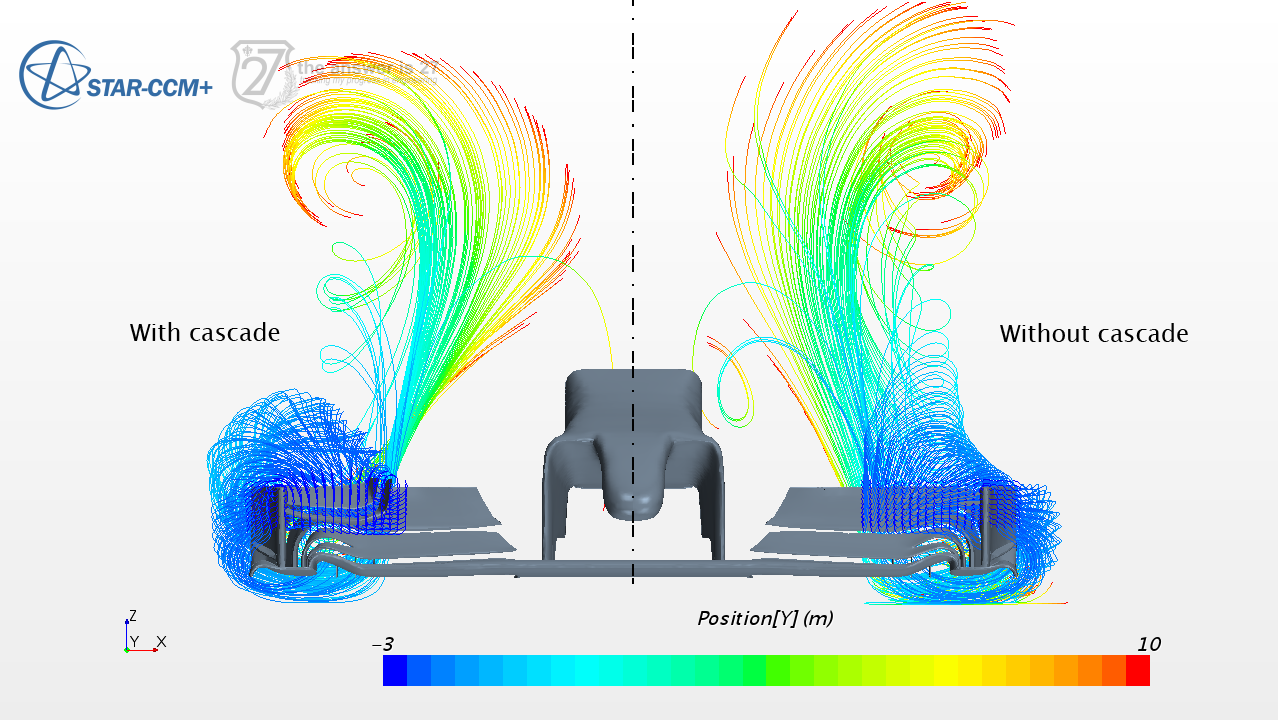
One might intuitively think that cascades contribute to generate downforce. But they don’t. At least not in this particular simulation. On the other hand, they do have a significant effect on drag. They increase drag. Then, why would anyone want to place a cascade if it increases drag and generates no downforce at all? Let’s see if the flow patterns give us a hint (take into account that there should be a wheel drafting on the wing).
Original configuration
No cascade configuration
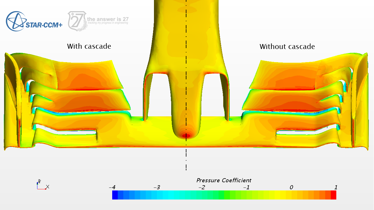
You can try to watch both videos at the same time. One of the thing we can appreciate in the simulation is that the cascade element stalls (recirculation flow) which partially explains its no contribution to downforce. But the cascade has also an effect in pressure distribution on the wing and flap elements as we can see in Figure 3. There is lower CP on the lower flap when the cascade the cascade is present which leads to slightly lower downforce.
Also, by looking at the following figure, it is not clear that the cascade serves its purpose by deviating the incoming flow from the tyre. The aileron stalling in this particular simulation may be the reason for this unexpected behaviour.
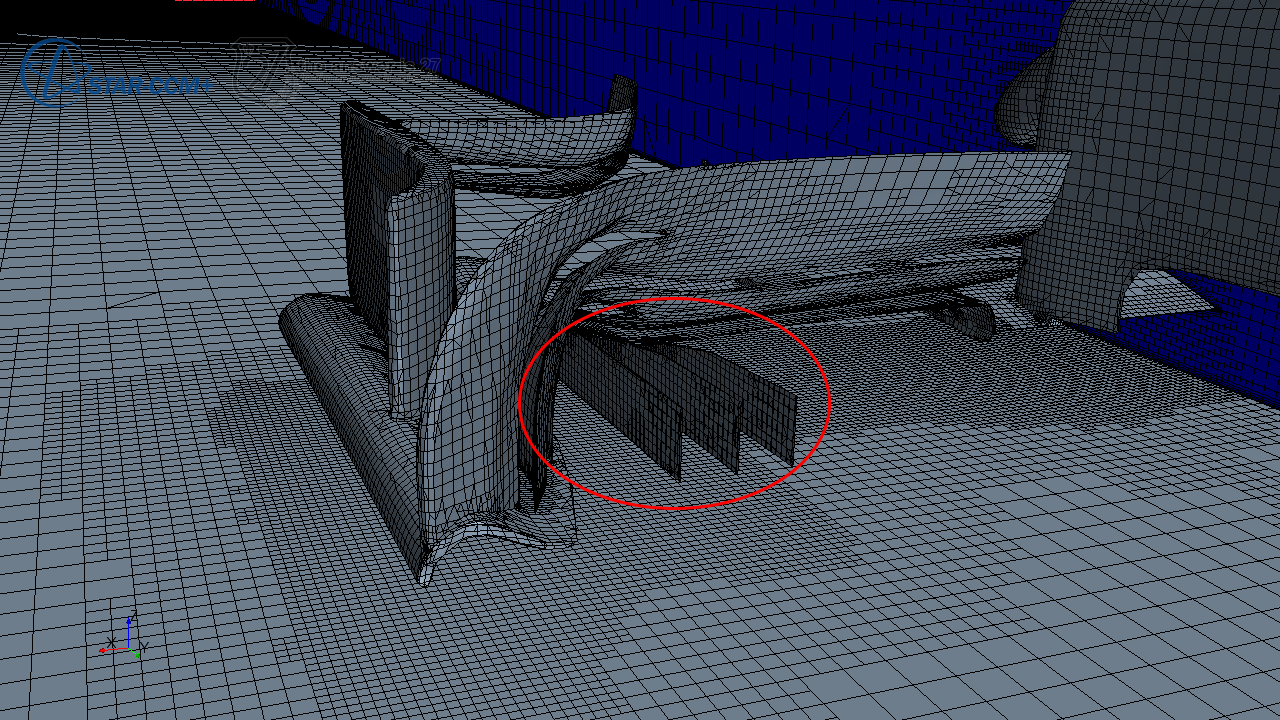
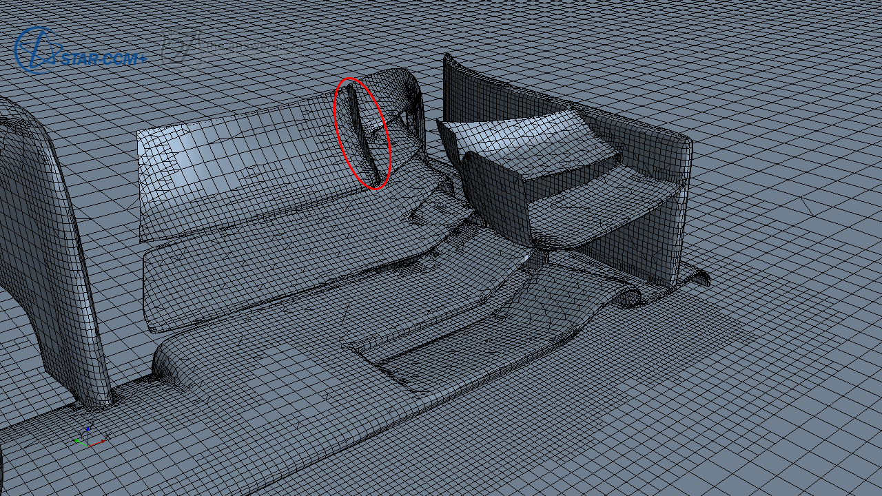
Diffuser and vane
The so called diffuser are three long plates which, I guess, have the purpose of straightening the flow while creating small vortices as can be appreciated in Figure 6. On the other hand, the vane will keep the high pressure area on the upper surface of the flap from fading towards the endplate as can be seen in Figure 7.
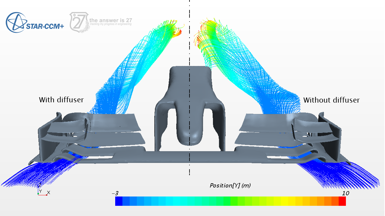
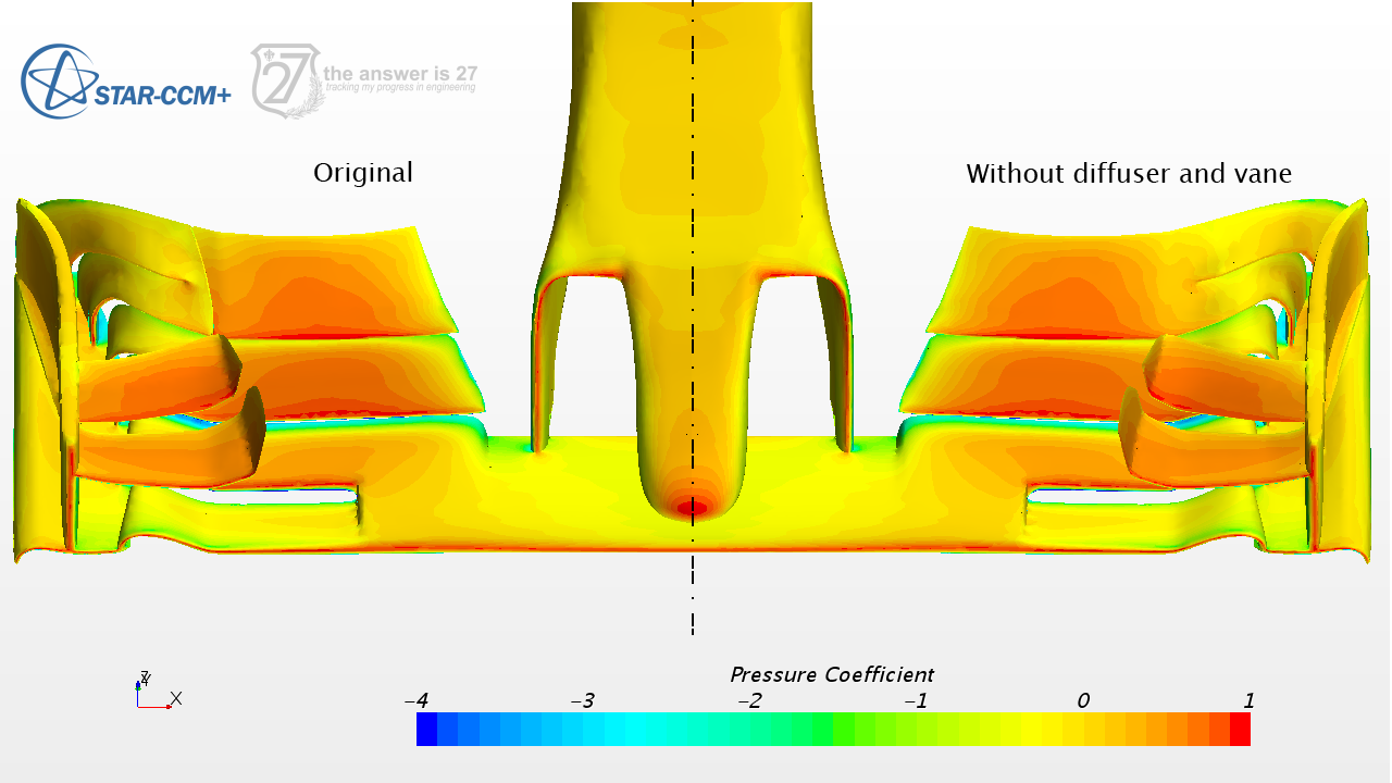
The total gain in drag by removing both vane and diffuser elements is of about 7 N at 200 kph. Of those 7 N: 1 N corresponds to shear stress distribution over the diffuser surface; 2 N are due to pressure redistribution over the lower surface due to the presence of the diffuser; and 3 N are due to pressure redistribution over the upper flap due to the vane.
Comments
Computational Fluid Dynamics simulations require of verification and validation. The latter, unfortunately, is something I cannot reach for. Thus, all the results herein presented are by no means representative of the actual performance McLaren’s aerodynamic packages.
Furthermore, the tyre, suspension links and all the chassis, albeit being downstream, have an impact in the aerodynamics of the front wing. The effect of drafting objects is something I will intend to address in the following post.
Acknowledgements
This study was possible thanks to CD-adapco’s Global Academic Program through which students have free access to individual licenses. Especial thanks to Juan David Barrera for providing the CAD geometry.