Drag coefficients for two Ahmed models at different vehicle spacing
This is an interesting academic exercise proposed in the book by Tu et al. [1] to analyse the aerodynamic drag and lift of two drafting bodies.
For that, a model simulation of two two-dimensional Ahmed models was developed. Each model had its own mesh continuum, the leading model being placed in static mesh with the dimensions of the fluid volume, and the trailing model placed in a smaller movable overset mesh. Total mesh size is ~150k cells.
Are CL and CD for the wing the same as those for the airfoil? The answer is a resounding NO! Not even close! Surprised? How can this be? —John D. Anderson [2].
Although a 2D solution will yield very different results to that of a 3D model, it allows for quick calculations as well as to detect certain trends. Experimental data by Watkins and Vino [3] is also shown so trends can be compared.
Contents
Boundary conditions
At the inlet, the velocity is set so that a Reynolds number of 2.3×10⁶ is obtained. The flow turbulent instensity is assumed to be 1.8%. The floor travels at the same speed as the air.
Results
Spacing was varied from 0.1 x/L to 4 x/L in steps of 0.1 to analyse the influence of drafting on the pressure distribution of each Ahmed model. Drag and lift coefficients for the 2D case is calculated per unit width.
Drag
We can appreciate that the presence of a trailing model has a beneficial effect on the leading model due to subsonic upstream disturbances. In other words. The trailing model fills up the space in between with a higher pressure than that of a single model.
This effect can be exploited in several circumstances. For instance, cycling teams can devise optimum cyclist positioning strategies in time trials as is shown by Blocken et al. [4]; although in this case cyclists are bluff bodies, and effects on drag for the Ahmed model can not be directly extrapolated. Truth be told, the Ahmed model is not the most aerodynamic model I’ve ever seen.
*Values at 2.9, 3.9 and 4.0 can be considered as outliers for reasons unknown. If looking at the pressure contours and velocity profiles later on, we can appreciate that there is no smooth transition from 2.8 to 3.0 through 2.9.
Lift
Lift on the model is generate due to the acceleration of the flow on its upper surface. In the 2D case we almost appreciate no variation in lift for the leading model. This can be due to important 3D effects taking place in the full scale model.
Pressure
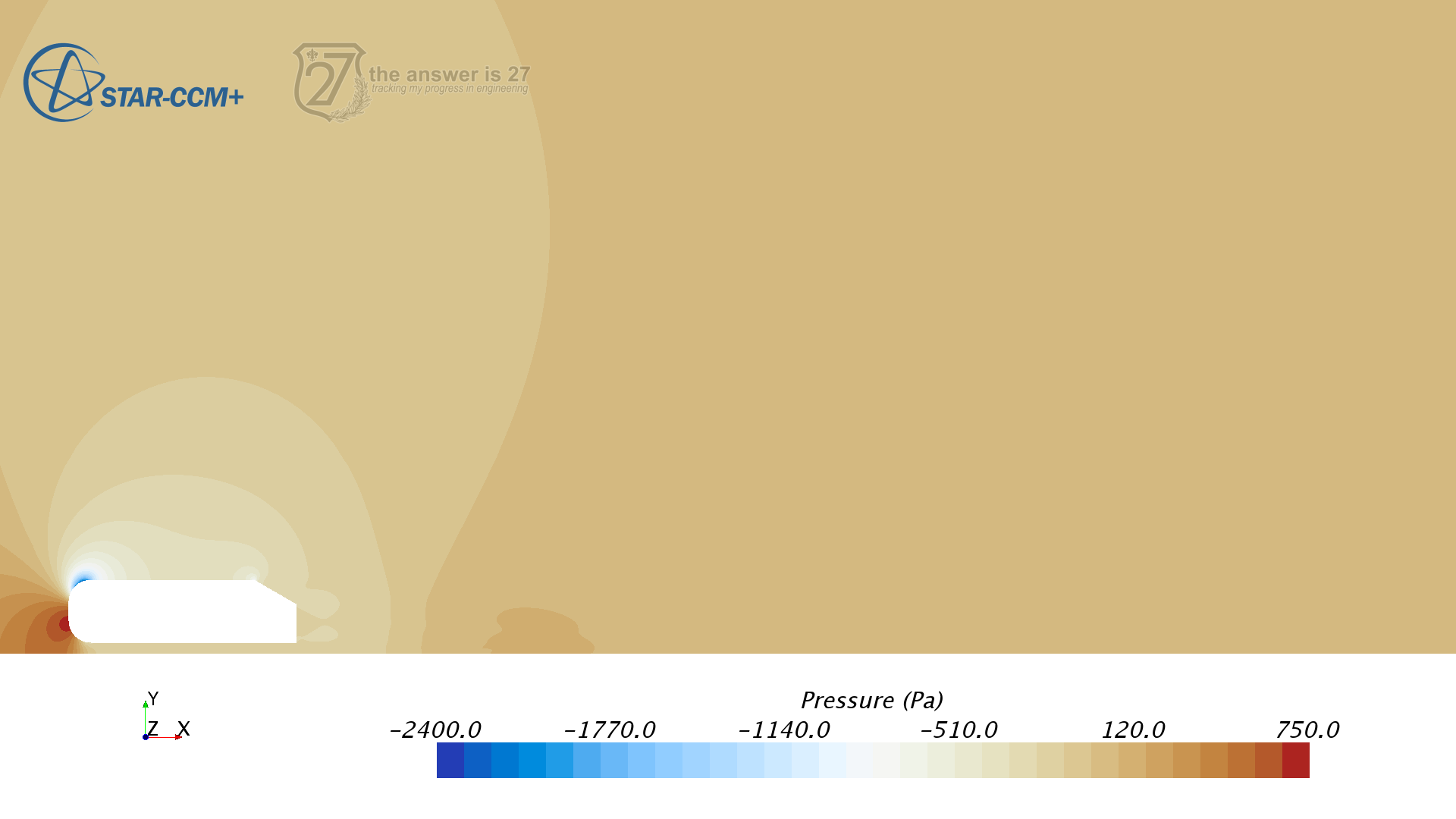
The closer the trailing model, the more it reduces the value of underpressure at the back of the leading model, leading to a drag reduction of the leading model. In addition, the presence of the leading model reduces the value of the underpressure at the back of the trailing model as can be seen by comparing the video with Figure 1 below. When the spacing is close, the benefit is mutual as the presence of the leading model also reduces the underpressure at the back of the leading model.
I wonder what’s the effect on Hamilton’s and Rosberg’s cars when they battle hand to hand. Although that case we’d have to take into consideration the DRS.

Figure 1. 2D pressure distribution for a single model.
Velocity
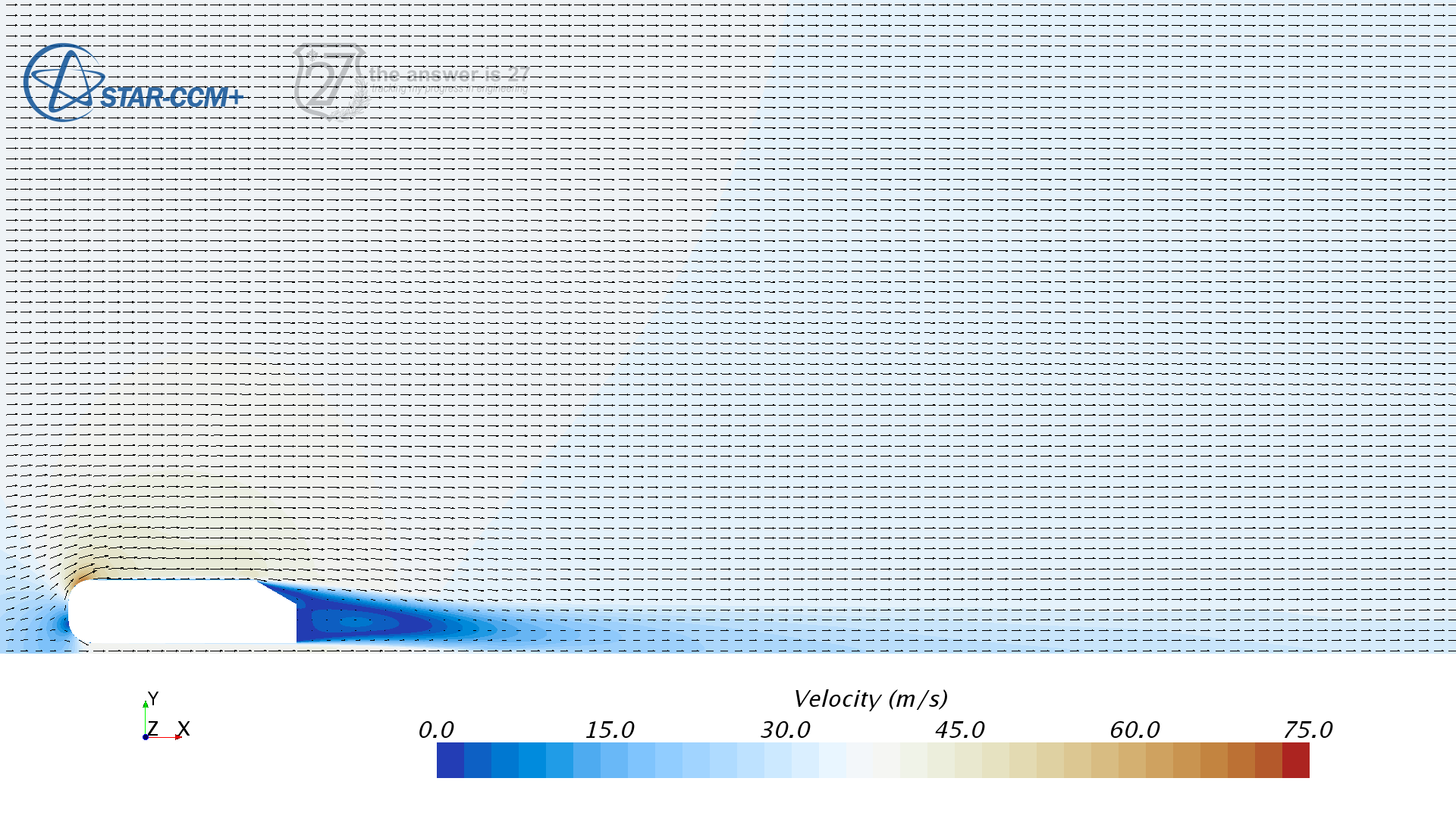
If we look at the velocity profile in 2D, we can appreciate the evolution of the trailing recirculation vortex as the gap increases. Also, the shape of the recirculation vortex of the trailing model is different from that of the model alone.

Figure 2. 2D velocity field for a single model.
Further considerations
Additional simulations can be carried out with different turbulence models to verify if the presence of outlying values is due to the model, or at different mesh setting to discard discretization effects.
This also shows us that the presence of a wheel can have significant effects on the drag and downforce generated by the front wing of a F1 race car.
References
[1] Tu, J., Yeoh, G. and Liu, C. (2008). Computational fluid dynamics. 2nd ed. Amsterdam: Butterworth-Heinemann.
[2] Anderson, J. (2007). Fundamentals of aerodynamics. 4th ed. New York: McGraw-Hill, p.392.
[3] Watkins, S. and Vino, G. (2008). The effect of vehicle spacing on the aerodynamics of a representative car shape. Journal of wind engineering and industrial aerodynamics, 96(6), pp.1232–1239.
[4] Blocken, B., Defraeye, T., Koninckx, E., Carmeliet, J. and Hespel, P. (2013). CFD simulations of the aerodynamic drag of two drafting cyclists. Computers & Fluids, 71, pp.435–445.
Appendix
https://gist.github.com/pfsq/0ca4e68f028ebfde3643
