
CFD on a Le Mans Prototype
I am following STAR-CCM+’s Tutorial Guide to get to know the CFD software before starting to work on my actual thesis. Surprisingly, in one of the first chapters we learn about Parts Based Meshing: External Aerodynamics using the geometry of a Le Mans Prototype (LMP) as the subject of study.
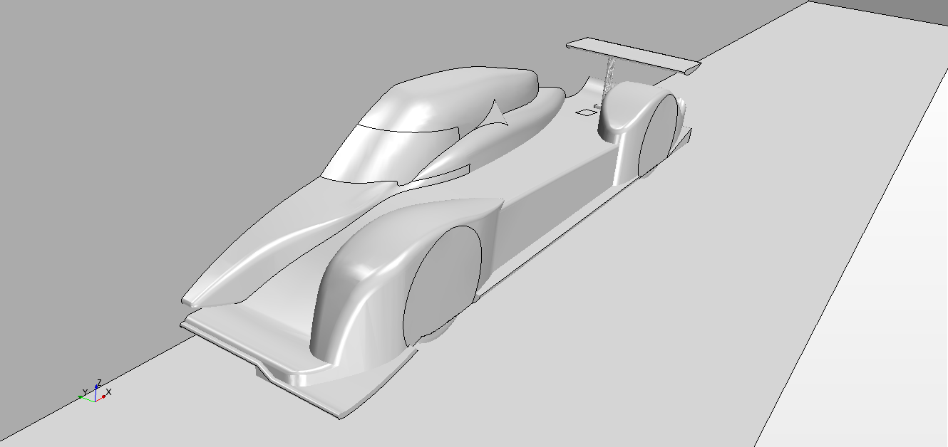
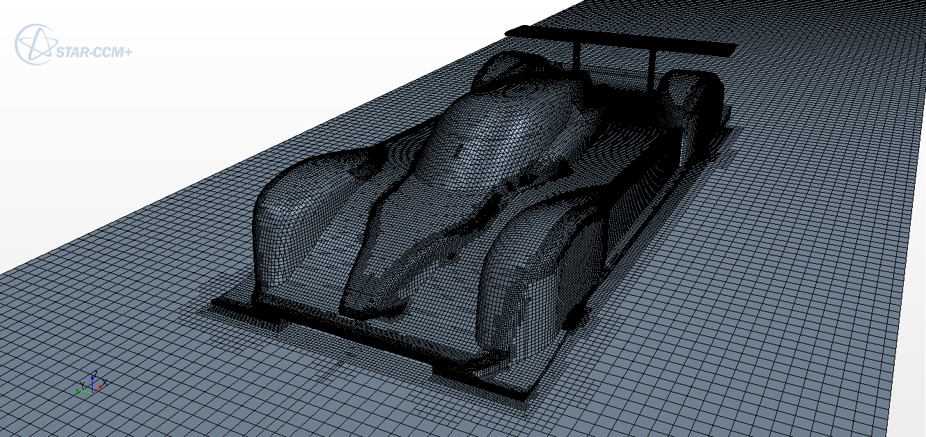
This part of the Tutorial is only about meshing, but, taking advantage of the fact that the mesh is already prepared and the boundaries are defined I will try to simulate the air flow around the LMP. For that I will follow the instructions provided by CD-adapco in their Best Practices for Vehicle Simulations, though I will skip some steps as for now I just want to get a first approximation to the solution.
Contents
Setting Up the Physics Models
Physic models define the primary variables of the simulation, including pressure, temperature and velocity, and the mathematical formulation. Here I will use turbulent and compressible flow.
Selecting Models
According to CD-adapco, either SST (Menter) K-Omega or Spalart-Allmaras Detached Eddy Simulation model is recommended for vehicle aerodynamics —both seem to give similar results.
The physics model used for this problem is:
- Time: Steady.
- Material: Gas.
- Flow: Coupled Flow.
- Equation of State: Ideal Gas.
- Viscous Regime: Turbulent.
- Reynolds-Averaged Turbulence: Spallart-Allmaras Turbulence.
Setting Initial Conditions
Initial conditions in a continuum specify the initial field data for the simulation.
In steady-state simulations, the solution ought to converge independently of the initial field. However, the initial field still affects the path to convergence, and with it the cost of computing power.
- Velocity: 150 kph.
- Static Temperature: 300 K.
- Turbulent Viscosity Ratio: 10.
- Reference Pressure: 101325 Pa.
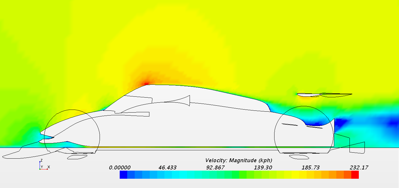
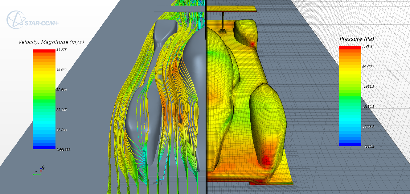
Preliminary results
After a couple hundred iterations we can show some of the results, though the solution has not fully converged.
The tutorial comes with the geometry for three different wing settings which I will try to test and compare. But that is something I will put off; in the meantime I have almost 3000 pages of tutorials ahead I want to look over.