
BMW E30 318i: engine management optimization
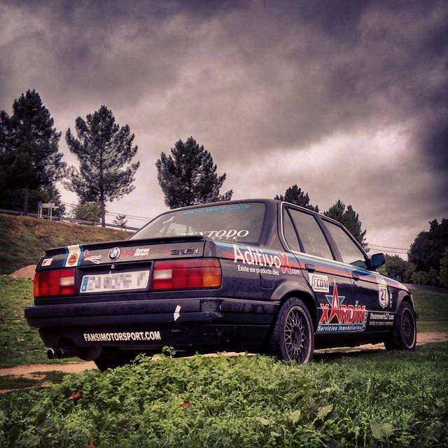
I’ve already talked about our race car, affectionately known as the “penco” —Spanish for nag—, in previous posts. The term “penco” is not fortuitous, as with only 113 hp the car was at the bottom of the entry list for the 24 hours of Braga in terms of horsepower. Nonetheless, we’ve seen that, in endurance racing, horsepower is not everything as was demonstrated by the 115 hp VW Golf III that took the victory against teams with up to 200 hp cars.
Our race car, like most vehicles from the early 1980s onwards, incorporates an engine control unit that control several actuators to ensure optimal engine performance. Therefore, by tuning the so called engine maps it is possible to achieve superior performance.
Contents
Engine control unit
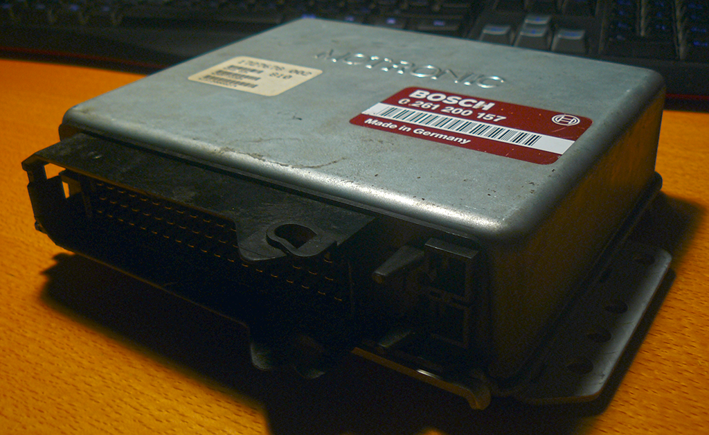
Our car fits a Motronic 1.3 digital engine management unit produced by Bosch. Its main function is to control the fuelling and timing in manifold-injection gasoline engines. It is characterized by the fact that the air is supplied through a mechanically adjustable throttle valve.
Engine control units consist primarily of input circuits, the ECU’s microprocessor, the program and data memory, and actuator triggering circuits.
![Signal processing in the ECU [1].](https://theansweris27.com/wp-content/uploads/2014/10/Gasoline-Engine-Management-265.png)
EPROM to EEPROM
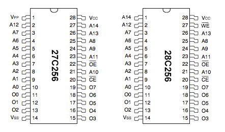
In the Motronic 1.3 engine management unit, the open- and closed-loop control operations are stored in a 256 kbit erasable programmable read only memory (EPROM), part number B57604, which is Bosch’s equivalent to a 27C256 DIL28. This memory —which stores the software in the form of binary numerical values arranged in data records— can be read using a programmer to obtain the variable data, characteristic curves, and maps used by the microcontroller during vehicle operation. The first lines of the hex dump, which can be edit in specific software packages such as WinOLS, are shown right below.
Offset(h) 00 01 02 03 04 05 06 07 08 09 0A 0B 0C 0D 0E 0F
000000000 85 0A F0 30 F0 51 D5 08 4E E5 09 B4 00 24 43 C1 ….ð0ðQÕ.Nå.´.$CÁ
000000010 C0 C2 AF C2 93 F5 C6 D2 AF 53 C1 3F 74 F4 25 C6 À¯“õÆÒ¯SÁ?tô%Æ
000000020 F5 C6 74 01 35 C7 F5 C7 43 C1 80 D2 93 75 08 0A õÆt.5ÇõÇCÁ€Ò“u..
000000030 80 67 B4 01 24 43 C1 30 C2 AF C2 92 F5 C4 D2 AF €g´.$CÁ0¯’õÄÒ¯
000000040 53 C1 CF 74 F4 25 C4 F5 C4 74 01 35 C5 F5 C5 43 SÁÏtô%ÄõÄt.5ÅõÅC
000000050 C1 20 D2 92 75 08 0A 80 40 B4 02 14 10 F1 06 D2 Á Ò’u..€@´...ñ.Ò
000000060 F1 7F E6 80 02 7F 1B C0 F0 12 70 70 D0 F0 80 26 ñ.æ€...Àð.ppÐð€&
000000070 B4 03 1A B2 F1 90 01 62 E0 A2 F1 92 E3 F0 75 83 ´..²ñ..bà¢ñ’ãðuƒ
000000080 A0 75 82 21 F0 75 82 05 74 00 F0 80 09 B4 04 04  u‚!ðu‚.t.ð€.´..
000000090 B2 EA 80 02 B2 10 75 08 64 85 F0 0A 22 90 44 AC ²ê€.².u.d…ð.".D¬
0000000A0 74 22 93 C3 95 3B 50 03 02 81 70 78 81 79 2E 7D t"“Õ;P...px.y.}
0000000B0 06 12 06 86 C2 D5 74 23 93 B4 FF 03 02 80 C2 12 ...†ÂÕt#“´ÿ..€Â.
0000000C0 81 9A 74 28 93 B4 FF 03 02 81 67 F5 F0 30 78 0A .št(“´ÿ...gõð0x.
0000000D0 30 03 04 C2 78 D2 79 02 81 67 E5 3B 70 03 75 68 0..ÂxÒy..gå;p.uh
0000000E0 32 D5 33 03 02 81 24 E5 F0 C3 13 F5 F0 B5 33 13 2Õ3...$åðÃ.õðµ3.
0000000F0 E4 A2 03 B3 92 E0 C3 95 31 70 6C E5 31 D2 E7 F5 ä¢.³’àÕ1plå1Òçõ
Although once programmed, the EPROM can be erased by exposing it to strong ultraviolet light source, this is a rather lengthy process —several minutes for UV lamps of convenient sizes— and most times impractical. Fresh data can then be entered using a programming unit.
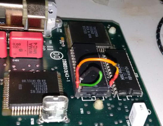
We found the 28C256 to be an ideal replacement chip, with the advantage of being an electronically erasable programmable read only memory (E2PROM). Only drawback is a minor difference in the pin-out, affecting pin #1 and #27.
When placing the 28C256 in circuit it is necessary to:
- Lift pin #1 of the 28C256 so it does not contact the VPP pad,
- Lift pin #27 of the 28C256 so that it does not contact the A14 pad,
- Solder, join, or bridge the lifted pin #27 to pin #28 of the 28C256 (tying WE high), and
- Blue wire pin #27 on the board to the lifted pin #1 of the 28C256 (connecting the address line).
And it works.
Fuelling and timing
As we mentioned earlier, M-Motronic ECUs control the fuelling and timing in manifold-injection gasoline engines, i.e., the amount of fuel injected per stroke and the advance angle of ignition point relative to the top dead centre (TDC).
Ignition timing can be adjusted to obtain:
- Maximum engine power,
- Maximum fuel economy,
- Prevention of engine knock, and
- Clean exhaust gas.
It is impossible to fulfil all the above demands simultaneously, and a compromise must be reached from case to case. In a race car like ours maximum engine power should be the goal although, for endurance series, maximum fuel economy has its perks too. Whatever the goal, knock should be always avoided as it may cause severe engine damage.
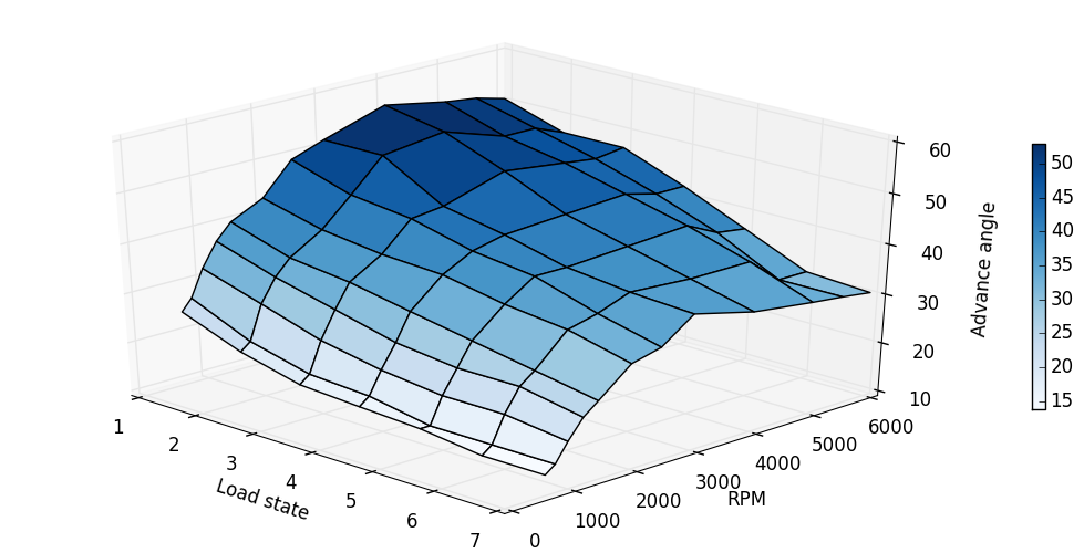
One of the most import variables used for determining injection quantity and ignition advance angle is the engine’s load state (see picture above). Different sensors are available to monitor engine load:
- Air-flow sensor,
- Hot-wire air-mass meter,
- Hot-film air-mass meter,
- Intake manifold pressure sensor, and
- Throttle valve sensor.
Load state, along with injector constants, defines the duration of the activation signal and the flow quantity at the injector —injection duration multiplied by the injector constant results in injected fuel mass—. The amount of fuel is so that an excess-air factor of λ ≈ 1 is sought after.
In addition, readings for ambient pressure along with data for engine and intake-air temperature provide the basis for corrections to compensate for pressure and temperature variations. This can be done by supplying additional corrections and/or revert to other maps to adapt to all operating conditions. Thus the mutual effects of torque, emissions, fuel consumption, preignition tendency and driveability can all be taken into account [2].
Remapping and rolling road test
Custom remapping for this car has been provided by DRS, with over 10-years experience in the field. Although a better response is readily noticeable, the new setup will be tested on a chassis dynamometer (rolling road) within a couple of weeks. DRS is giving me the opportunity to learn not only how to remap our own race car, but also how to optimize the original program in the ECU of Diesel and petrol vehicles, by collaborating with them as a dealer expanding their presence in Spain. At the same time, a workshop with an eddy current brake rolling road near home will offer me full access to their facilities, ideal to validate new map settings. More on that soon.
References
[1] Reif, K. (2014). Gasoline engine management. Friedrichshafen: Springer Vieweg.
[2] Steinbrenner, U., Barho, H., Böttcher, K. et al. (2000). M-Motronic engine management. 4th ed. Stuttgart: Robert Bosch GmbH.