
First hands-on with I2C
I2C, as defined by Wikipedia, is a multimaster serial single-ended computer bus invented by Philips used for attaching low-speed peripherals to a motherboard, embedded system, cellphone, or other electronic device. But most importantly, it is the protocol that the barometric pressure sensors we will be using relies on.
I won’t be using Arduino for this project. Instead, a 20 pin PIC18LF14K50 will do all the work.
So as to use the I2C protocol, first of all we have to take a look at the datasheet for the BMP085 digital pressure sensor. There we get a module address like the one shown below,
| A7 | A6 | A5 | A4 | A3 | A2 | A1 | W/R |
| 1 | 1 | 1 | 0 | 1 | 1 | 1 | 0/1 |
for which we can declare a new char variable,
unsigned char address = 0xEE;
This way the I2C protocol will know to which sensor send commands, and from which sensor read measured values.
Adafruit provides some code and libraries to use with the pressure sensor. But here I’ll just be using some basic I2C commands so as to understand the protocol internals, which can be summed up as:
- Which module I want to access,
- What register I want to read from or write into,
- Read or write it.
This is exemplified in more detail in the following diagram and code snippet:
![Figure 1. Timing diagram read 16 bit A/D conversion result [BMP085 Datasheet]](https://theansweris27.com/wp-content/uploads/2013/07/bmp085-19.jpg)
Figure 1. Timing diagram read 16 bit A/D conversion result [BMP085 Datasheet].
#include <i2c.h>

void main(void) {

	OpenI2C(MASTER, SLEW_OFF);		// Initialize I2C, PIC18 as MASTER, 100 kHz

	SSPADD = 9;						// CLK = FOSC/(4*(SSPADD + 1))

	while(1) {

		StartI2C();

		WriteI2C(address);			// Module address from which we want readings

		WriteI2C(sensor);			// Register address where the value is stored

		RestartI2C();

		WriteI2C(address|0x01);		// Module address, read mode

		msb = ReadI2C();			// Read value sent over I2C, msb

		AckI2C();					// Acknowledge by Master

		lsb = ReadI2C();			// Read value sent over I2C, lsb

		NotAckI2C();				// Not Acknowledge by Master

		StopI2C;

		value = (msb << 8) | lsb;	  // 16 bit result

	}

}
Now we can run some simulations with design software like the Proteus Design Suite; but as we don’t have the BMP085 available in the library, we will use a different sensor instead, but similar in concept.
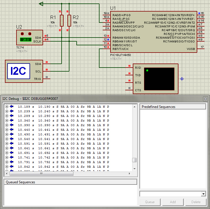
Figure 2. Component assembly in ISIS Proteus.
In Figure 2 we have a quite simple assembly with an I2C debugger. Though this particular temperature sensor has only 8 bit temperature registers, in the I2C debug window we can see the data structure sent over the bus. We can clearly identify:
- S: Start
- 9A: Module address
- A: Acknowledge
- 00: Register address
- Sr: Reset
- 9B: Module address, read mode (0x9A|0x01)
- A: Acknowledge
- 1A: 8 bit temperature reading
- N: Not Acknowledge by Master
- P: Stop
In the TC74 temperature sensor, the value read from the I2C bus equals temperature reading, i.e., 0x1A = 26. But with the BMP085 barometric pressure sensor, raw data will have to be processed as to get actual temperature and pressure values as shown in Figure 3; but that calls for another post.
![Figure 3. Calculating pressure and temperature from BMP085 [BMP085 Datasheet].](https://theansweris27.com/wp-content/uploads/2013/07/bmp085-14.jpg)
Figure 3. Calculating pressure and temperature from BMP085 [BMP085 Datasheet].