
Amateur Rocketry. The Timer0 Module
The Timer0 is one of the three built-in timers inside a PIC18 microcontroller. According to the Datasheet, the Timer0 module incorporates the following features:
- Software selectable operation as a timer or counter in both 8-bit or 16-bit modes
- Readable and writable registers
- Dedicated 8-bit, software programmable prescaler
- Selectable clock source (internal or external)
- Edge select for external clock
- Interrupt-on-overflow
For this project we will use the module as a timer in 16-bit mode. That will allow us to get a specified sample rate of 10 or 20 Hz, depending on what the conversion speeds of the sensors allow us.
The Timer0 has several registers to it which control all aspects associated to its operation (see Datasheet for default values and more information):
| Name | Bit 7 | Bit 6 | Bit 5 | Bit 4 | Bit 3 | Bit 2 | Bit 1 | Bit 0 |
| TMR0L | Timer0 Register, Low Byte | |||||||
| TMR0H | Timer0 Register, High Byte | |||||||
| INTCON | GIE | PEIE | TMR0IE | INT0IE | RABIE | TMR0IF | INT0IF | RABIF |
| T0CON | TMR0ON | T08BIT | T0CS | T0SE | PSA | T0PS2 | T0PS1 | T0PS0 |
| TRISC | TRISC7 | TRISC6 | TRISC5 | TRISC4 | TRISC3 | TRISC2 | TRISC1 | TRISC0 |
INTCON: Contains various enable, priority and flag bits,
- GIE: Global interrupt enable(1)/disable(0) bit
- PEIE: Peripheral interrupt enable(1)/disable(0) bit
- TMR0IE: TMR0 overflow interrupt enable(1)/disable(0) bit
- TMR0IF: TMR0 overflow interrupt flag bit
T0CON: This is the Timer0 Control Register,
- TMR0ON: Timer0 on(1)/off(0) control bit
- T08BIT: Timer0 8-bit(1)/16-bit(0) control bit
- T0CS: Timer0 counter(1)/timer(0) select bit
- T0SE: Timer0 source high-to-low(1)/low-to-high(0) edge select bit
- PSA: Timer0 prescaler assignment bit, off(1)/on(0)
- T0PS2..T0PS1: Timer0 prescaler select bits
Now, lets say that we want get samples at 10 Hz. The value of Timer0 will then be defined by
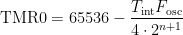
If we have the microcontroller running at 4 MHz (Fosc) and we want to gather samples at 10 Hz (1/Tint), knowing that the prescaler is defined in the form 1:2n+1 with n from 0 to 7. Iterating in the equation above, we need a prescaler with n = 0 (T0PS = 0b000) so that TMR0 > 0, which yields a value of 15536 = 0x3CB0,
| TMR0L | 0xB0 |
| TMR0H | 0x3C |
Following, we can see a snippet of how the code would look like:
#include
void High_Int_Handler (void);
#pragma code High_Int = 0x08		// high priority interrupt vector

void High_Int(void)	{

	_asm goto High_Int_Handler _endasm

}
#pragma interrupt High_Int_Handler

void High_Int_Handler (void) {

	if (INTCONbits.TMR0IF) {

		INTCONbits.TMR0IF = 0;		// set Timer0 flag back to '0'

		TMR0H = 0x3C;

		TMR0L = 0xB0;
		bmp085_get_cal_parameters();

		bmp085_get_ut();

		bmp085_get_up();

		bmp085_get_temperature();

		bmp085_calpressure();

		...

	}

}
void main(void) {

	// Initializations
	INTCONbits.GIE = 1;				// global interrupt enable

	INTCONbits.TMR0IE = 1;			// TMR0 overflow interrupt enable
	// Timer0 configuration

	T0CON = 0x80;					// Timer0 on, 16-bit, timer mode, prescaler on, n = 1

	TMR0H = 0x3C;

	TMR0L = 0xB0;
	while (1);

}