
Aerodynamics of rear wing mountings
Rear wings are an indispensable feature in modern racing since Colin Chapman successfully introduced the concept in Formula 1 during the late 1960’s. And like many innovations —unless the FIA or FOM decide otherwise—, it stayed.
Nowadays though, wings in F1 with their complex shapes and intricate designs are nothing like what they were back then. What’s more, they’re not just about generating downforce anymore; but that’s a story for another time.

In this article we’re going to focus on wing mountings, using for that a more conventional a dual-element wing design with constant airfoil profile; similar to the one used for the 2020 DTM season (above picture). We already analysed this very same geometry in a previous article, using STAR-CCM+; but I’m switching to OpenFOAM this time. Another difference from previous simulation is that this time we have placed the wing 15 cm from the ground.
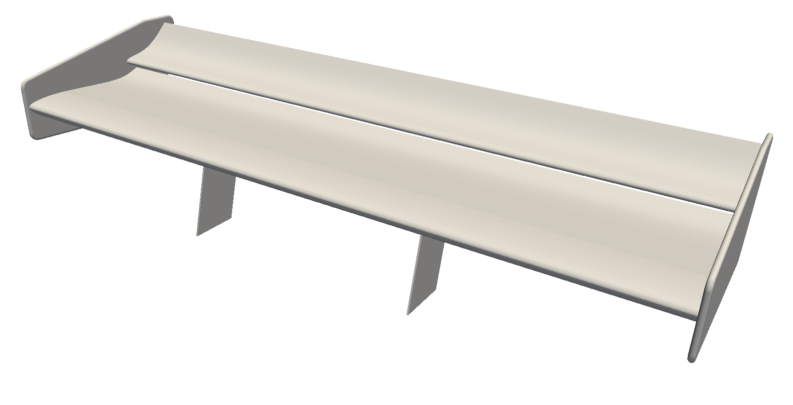
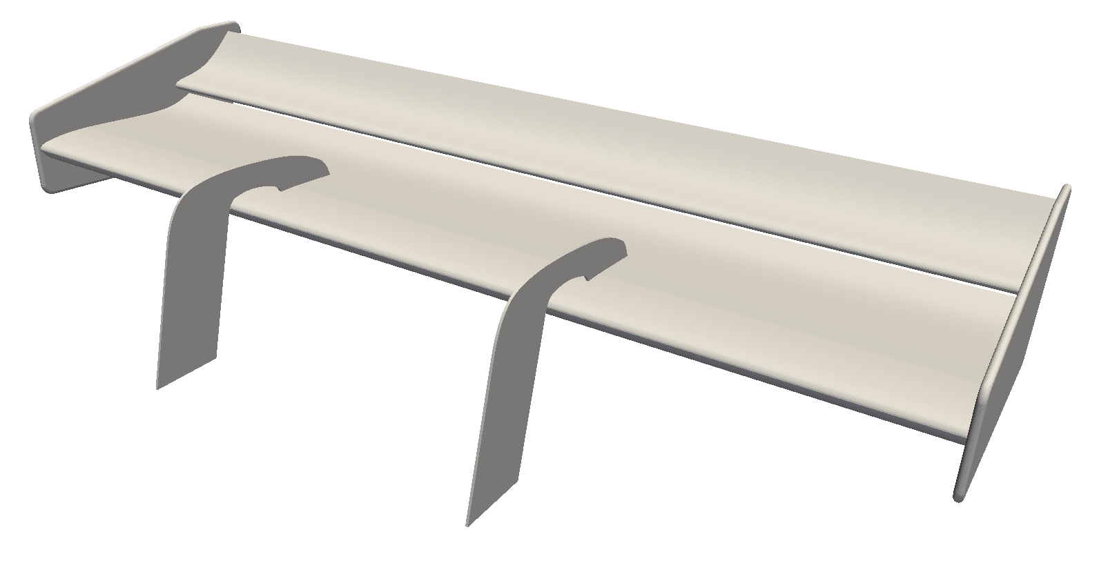
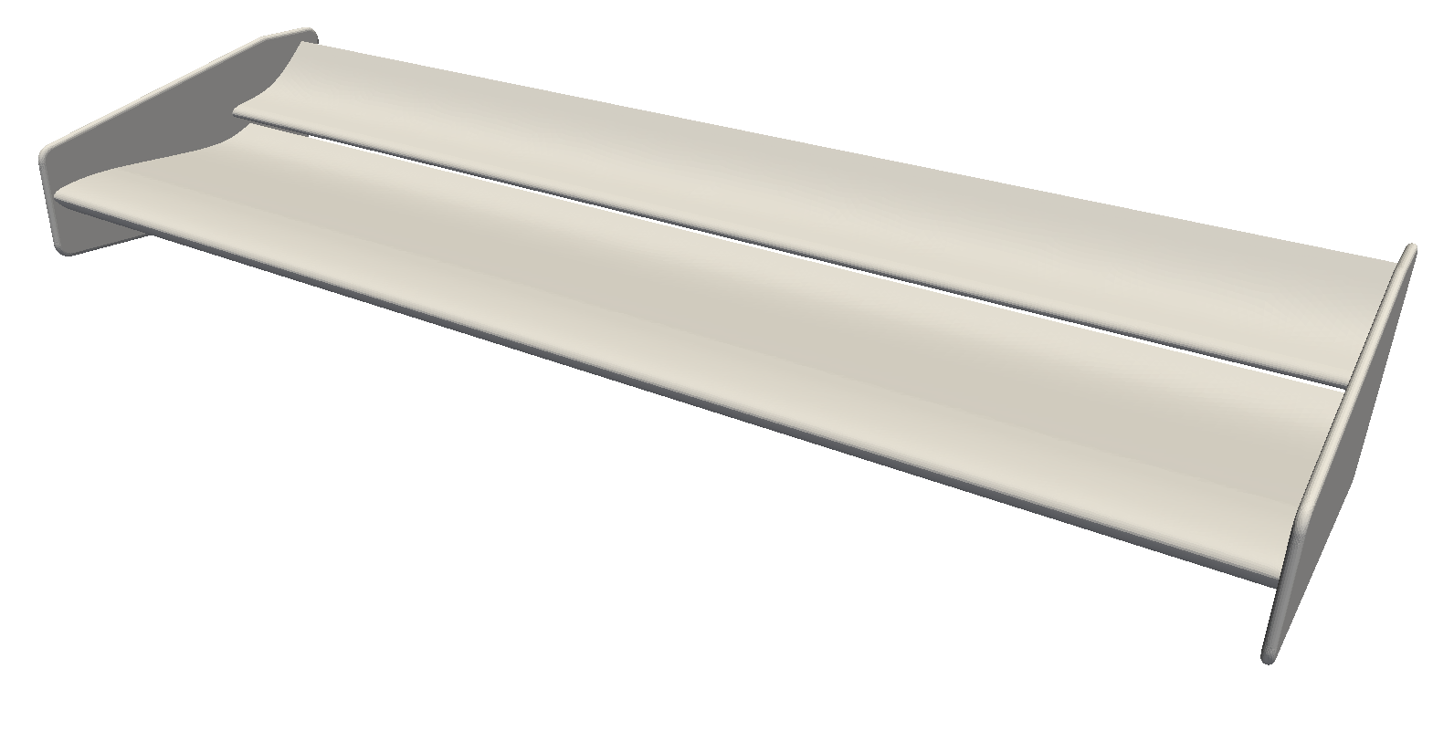
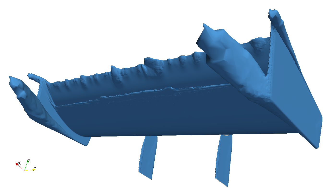
In the images below we can see the three configurations that have been tested: a baseline configuration without any mountings to have as a reference (bottom picture); a conventional suction side mounting (upper left); and the more recent trend pressure side mounting (upper right).
The floor and the walls of the virtual tunnel are of the slip boundary condition. For the floor, this is an unrealistic boundary condition; but to be fair, a rear wing should not be analysed on its own, but considering its location within the vehicle on which she will be mounted. Should we update the DrivAer model and add a rear wing to her? In any case, in this article we are focusing solely on studying the effect the different rear wing mountings have on the performance of the wing.
Contents
Downforce
When we fit a wing onto a racecar, we are looking for some extra downforce to keep our car gripped to the ground. So, how does the wing mounting affect its ability to generate downforce?
It is well known that the suction side of a wing contributes much more to lift/downforce than the pressure side; which is why most of the ancillary on airplane wings are located at the lower side. On racecars, having the wing mounting attached to the pressure side seems like a more recent trend. But, is it really effective? Let’s see.
As we can see in the chart, placing the mounting on the underside of the wing (suction side) reduces the amount of downforce provided by the assembly by ~2.5 %. On the other hand, the swan neck approach, in this case, has a negligible effect on downforce. So yes, it seems quite effective.
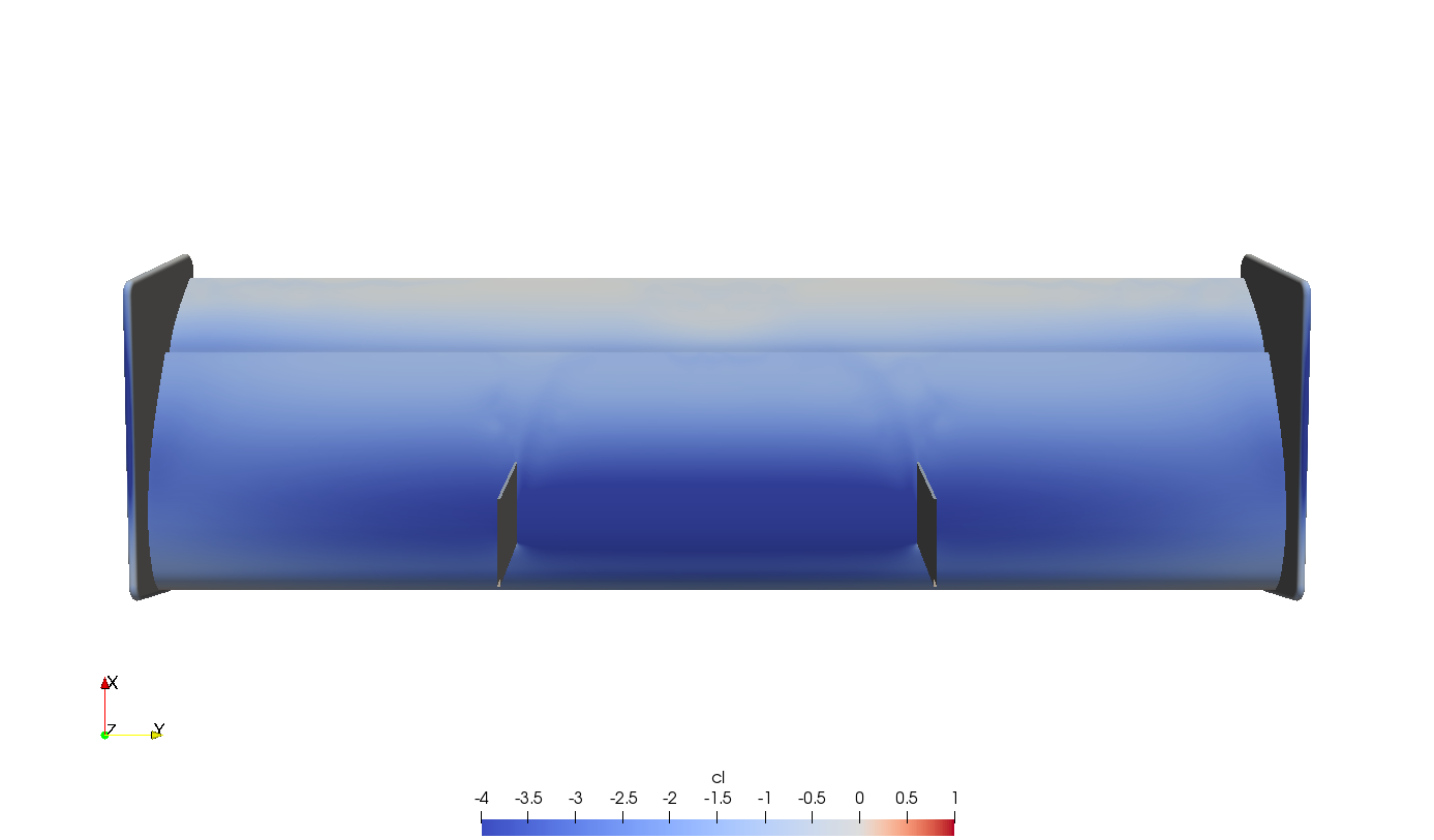
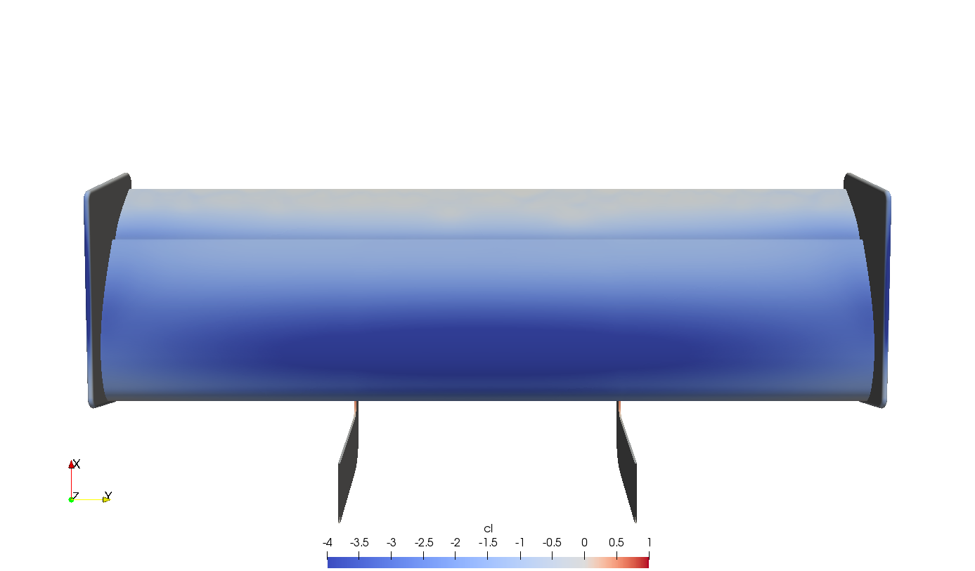
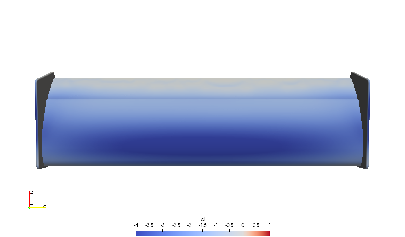
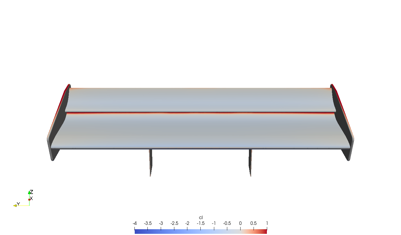
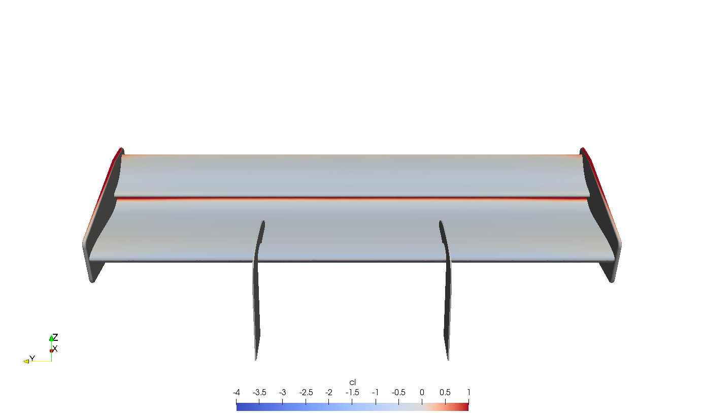
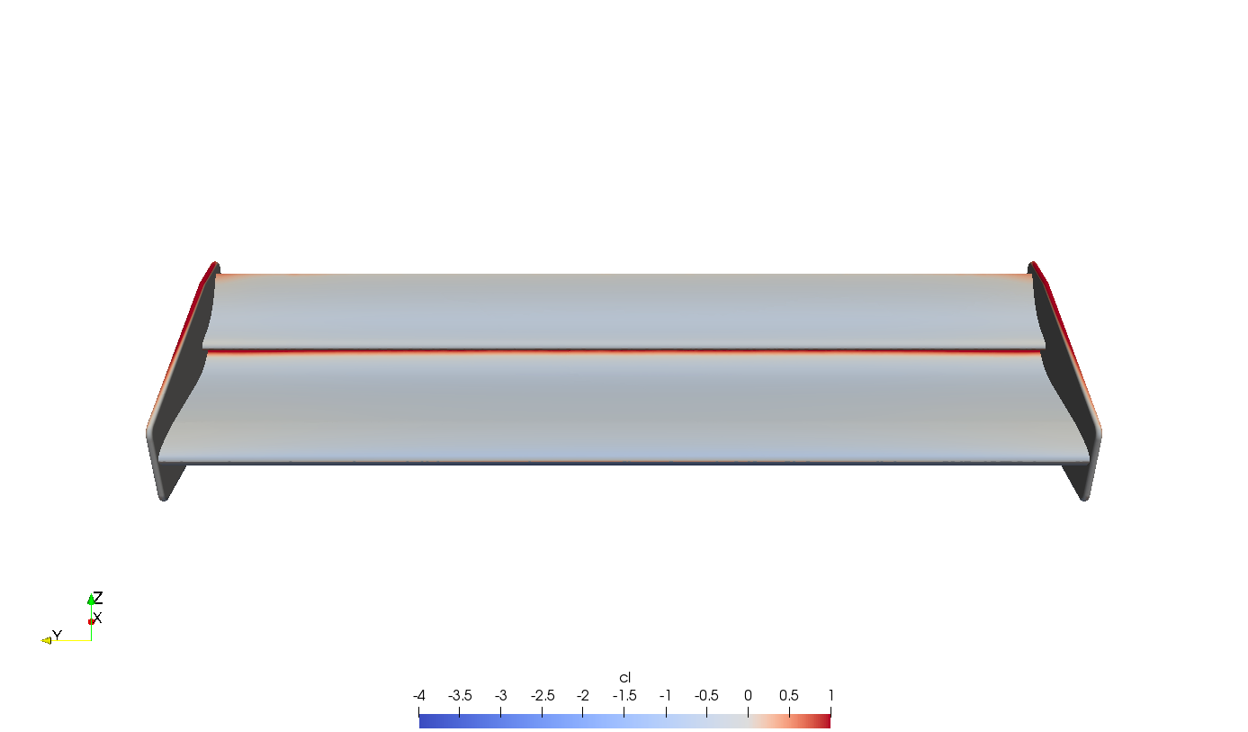
Why is that so? Well, if we take a look at the pictures below, where surface is coloured by cz, we can see that the lower surface is the main contributor to downforce (dark blue) while the upper surface is almost neutral (light blue-grey colour).
Total pressure
It is readily apparent that placing the mountings at the bottom of the wings disturbs the flow in this area. I was also expecting to see some wake out of the swan neck mounting to disturb the flow, though, that doesn’t seem to be the case.


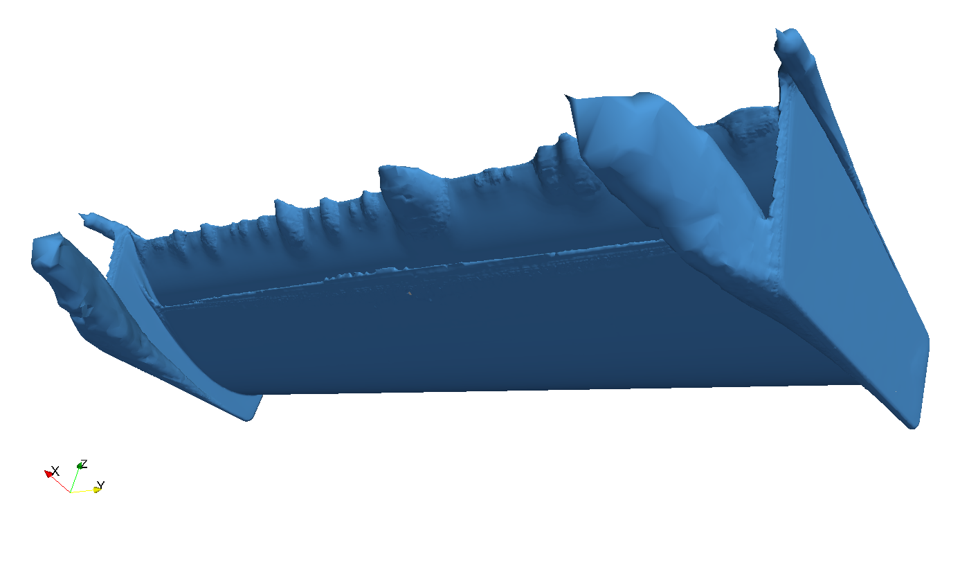
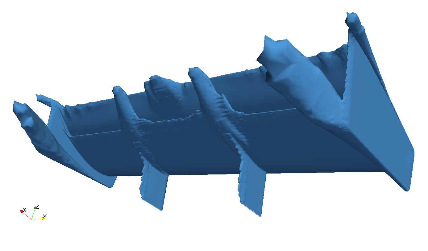
In the pictures shown above we can see two different ways of displaying total pressure losses. The top images show running slices of total pressure coefficient —in a scale from -1 to 1—, while bottom pictures represents the 0 total (relative) pressure iso-surface. As total pressure is the result of bringing the flow isentropically to rest, the regions of decreasing total pressure represent that the flow is dissipating part of its kinetic and potential energy through viscous shear stress in the zones of high turbulence. Being the suction side a delicate area, placing the wing mountings on the lower surface favours flow detachment which accompanied by greater turbulence in the region —we can see that through total pressure iso-surface.
Drag
In terms of drag, the variation is very little between the wing mountings studied. As we can see in the following chart, differences are below 0.5 %.
This values are not considering the contributions of the mountings; only the dual-wing elements and endplates. The mountings are thin structures, so the additional pressure drag that can come from them is very little (+1.5 % and +1.9 % for upper- and underside mountings, respectively); and surface shear usually contributes little to the total drag (about 3 % of total drag for those wings).
Summary
We have seen that the swan neck type of wing mounting provides some benefits in terms of downforce with very little penalty on drag. However, this has been studied with the wing in isolation, so you should expect some further analysis using the DrivAer model as our reference car.
References
Abbott, I. H., & VonDoenhoff, A. E. (1959). Theory of wing sections: including a summary of airfoil data. New York, NY: Dover Publ.
DMSB – Deutscher Motor Sport Bund e. V. (2018). Technical regulations. Retrieved from https://www.dtm.com/en/regulations/technical-regulations
Fagnan, R. (2018). The first appearance of wings on Formula 1 cars. Retrieved from https://www.motorsport.com/f1/news/1968-first-wings-f1-1000902/
Lopez, J. (2018). In the hunt for a repeat performance. Retrieved from https://www.topspeed.com/cars/audi/2018-audi-rs-5-dtm-ar180363.html
McBeath, S. (2015). Competition car aerodynamics: a practical handbook (3rd ed). Poundbury, Dorchester: Veloce Publishing.